
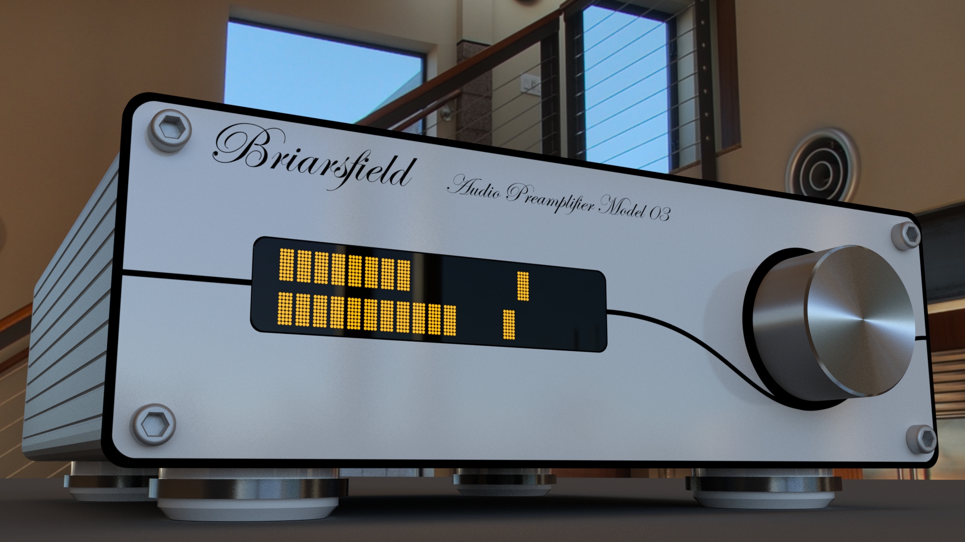
'Model 03' Preamplifier
Design spec:
A minimalist, high end miniature audio preamplifier with an elegant, single point user interface
Inspiration:
- The features I would use myself
Features
Minimalist UX:- Short press while powered on toggles between volume and input select control
- LED display returns to VU meter display after short timeout
Pure sound:
- Volume control by reed relay stepped attenuator matrix; no variable controls in signal path
- Audio switching by reed relays, NOT transistors or switches with long wiring runs
- Short signal paths
- Emphasis on D.C. coupling throughout (good phase and natural bass response)
Detail
I came across an LED matrix display and wondered if it would work well as a VU or bar graph meter. After digging up technical data (most of these displays are based on the old Hitachi HD44780, albeit with some odd caveats) and a couple of hours writing a code library, I had a set of functions where I could write text to the screen at will and from this came a prototype VU bargraph working on an Arduino. Gaining the speed necessary to get smooth bargraph motion is not as simple as it seems; to update each segment, both character ID and position have to be written, each followed by a clock pulse to instruct the display to read the data and update its display.
 Working VU meters on LED display - cursor shapes are just placeholders
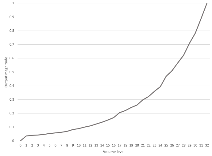 Reed relay stepped attenuator characteristic. Step 0 is full mute
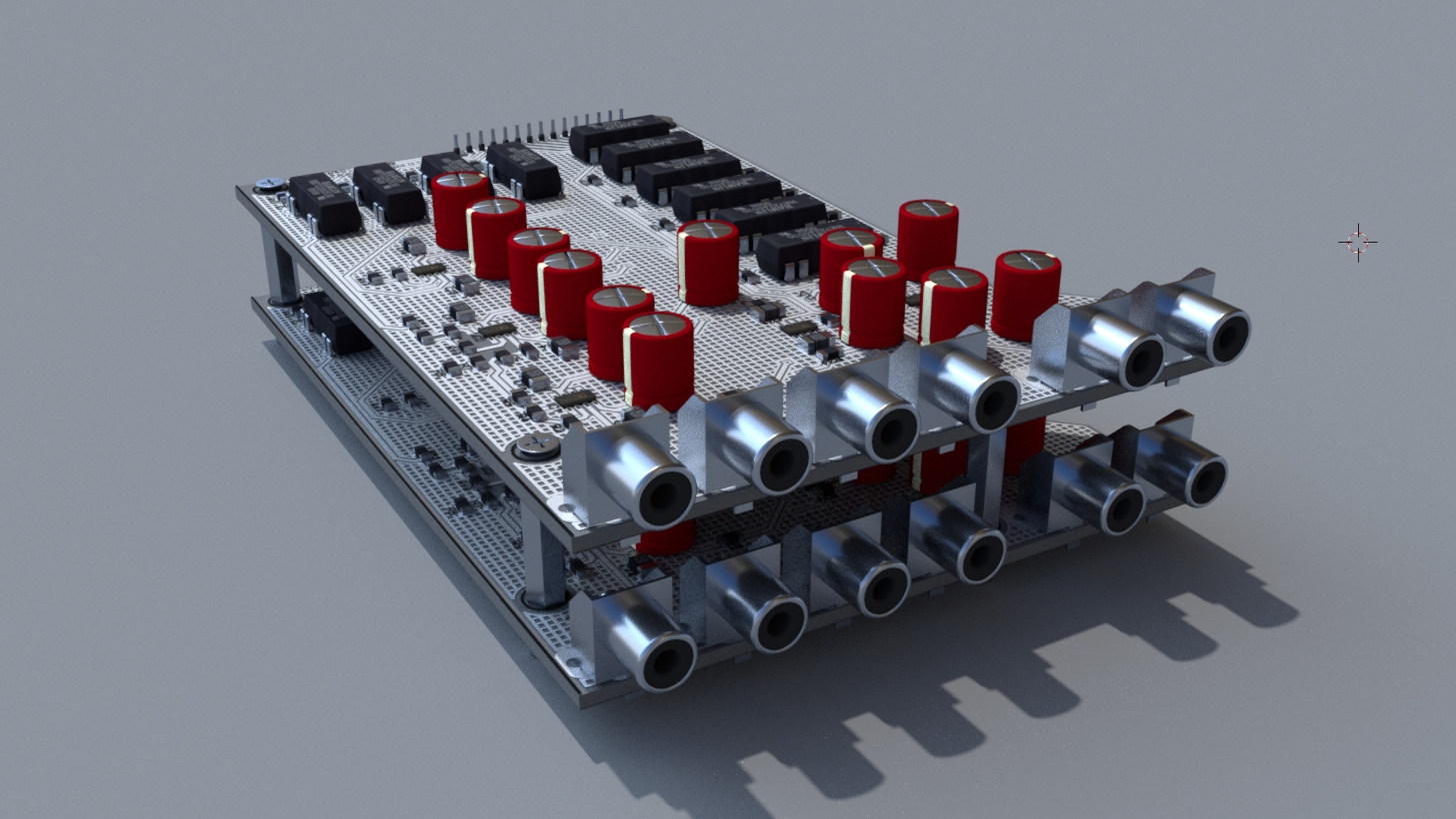 Rendered main assembly with fully designed PCBs
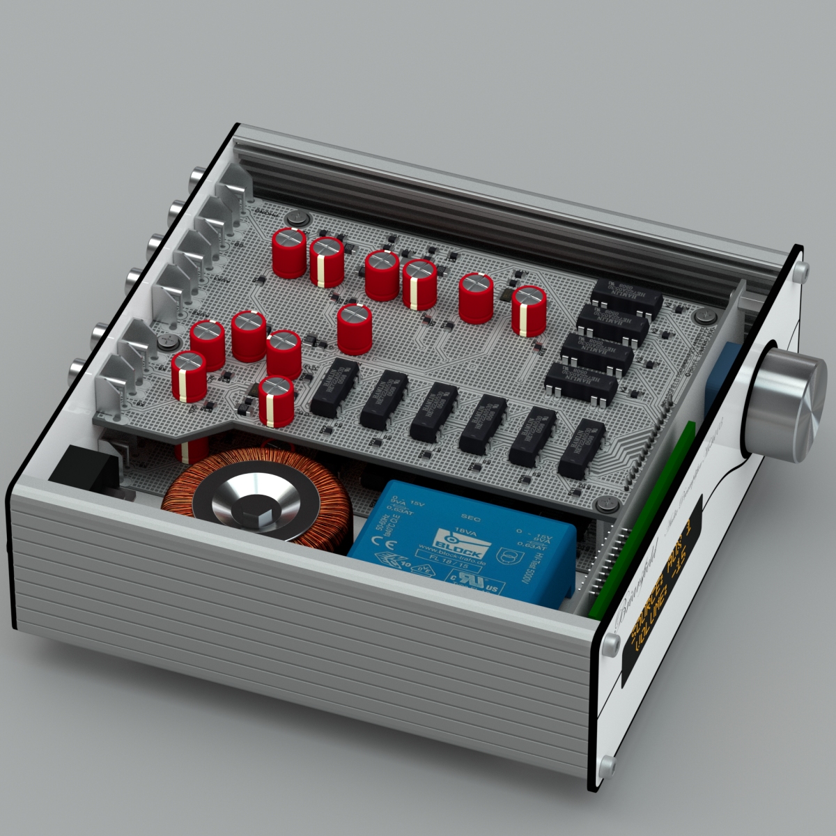 Packaged prototype design
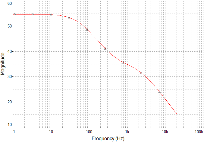 Response of the phono stage
Both displays I tested on struggled to load data reliably in less than 1 millisecond (this loading has to be done AFTER the data has been written, so compounds any delay in doing that). Add to this that individual output writes using standard Arduino libraries are relatively slow (around 30uS each on the Mega 2560 I tested with), this meaning that each character write takes around 500us, in addition to the 1ms pulse required to load the data after it's been written; this may not sound like much but when you consider the display has 32 positions which need to be written individually and the majority of these may need updating tens of times per second, a display coded this way runs like a slideshow.
Switching ports directly using bit masking and some imaginative coding to only update the changed segments proved faster by order of magnitude. Audio input to the meters is via an averaging circuit, the averaging time constant dictating the rise/fall time of the display, e.g. how much the level bars 'float'.
Volume control is via a 5-bit reed relay array, arranged to give 32 steps of true logarithmic volume level, plus a total audio mute via relays at the output. Input selection is also by reed relays; I did trial some programmable gain devices but was unconvinced by their performance. All relays are switched straight from a microcontroller, in the case of the volume control, in a binary type port arrangement. Maximum volume increment or decrement speed is software limited, to prevent glitches occurring through any switching overlap of the relays.
User input is via an Alps brand rotary encoder. I had never realised how noisy the output of these encoders were; just getting the microcontroller to reliably detect the encoder's pulses was a challenge, the switch bounce is really bad. The press function of the encoder (for mute and standby control) is an additional digital input.
The user interface is simple; a long press of the dial toggles between power on and standby, short presses while on toggle between input selection and volume control mode, shown on the display. After a short timeout, the display returns to bargraph mode; rotating or pressing the dial returns the display to control mode.
The power supply is two separate circuits; standby, logic and relay power is supplied through a single 5V supply rail, always live; in the prototype this is shown as a regular power transformer but using a switch mode would be considered. In standby mode, the microcontroller switches off all function except for an interrupt routine which detects user interaction with the control dial. Power for the audio circuitry is via a separate low noise power supply, primary switched by the standby circuitry. Power on/off mute is also handled by the microcontroller to prevent spurious pops or clicks. All microcontroller function is contained on a PCB attached to the unit's front panel with only D.C. power, relay drive and audio feedback (for the bargraph VU) shared with the separate audio assemblies. This modular approach helps ensure immunity from high frequency noise transmission from the controller's clock circuitry. Ground planes on the audio PCBs are hash poured to increase EMI immunity. Each audio circuit is supplied via a tuned RC filter to increase immunity to power supply noise.
The phono stage is a twin op-amp circuit which I have used in the past, handling the three stages of de-emphasis of the standard RIAA spec, but without the IEC revision's subsonic filter; the frequency curve shows flat response from the lowest filter pole to D.C., in reality there is the option for an input capacitor to protect the turntable's cartridge against damage from fault within the preamp, no matter how unlikely. The input on the prototype design suits MM type cartridges, with either PCB jumpers or rotary switches on the rear panel for resistive and capacitive load adjustment.
More soon...
